
Graphene Heating Films for Automotive Batteries
Graphene heating films are thin-film heating elements that generate heat through the Joule-heating effect when an electric current passes through a conductive material. They can be designed as flexible, thin, planar heaters for low-temperature heating of automotive traction batteries, battery-pack thermal management, and some low-voltage auxiliary-heating applications.
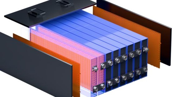
Graphene heating films are thin-film heating elements that generate heat through the Joule-heating effect when an electric current passes through a conductive material. They can be designed as flexible, thin, planar heaters for low-temperature heating of automotive traction batteries, battery-pack thermal management, and some low-voltage auxiliary-heating applications.
1. Main Materials Used in Graphene Heating FilmsGraphene conductive materials
Graphene powder, graphene nanoplatelets (GNP), reduced graphene oxide (rGO), and similar materials are used to form a conductive network that generates heat when energized.
Resins and dispersants
PVB resin, acrylic resin, epoxy resin, and additives such as dispersants and wetting agents help improve graphene dispersion, film formation, and adhesion.
Electrode materials
Copper foil, copper strips, silver paste, and similar materials deliver current, reduce contact resistance, and help the heating layer operate uniformly.
Substrates and insulating materials
PET, PI (polyimide), PEN films, silicone, and insulating adhesive films support the heating layer and provide electrical insulation and protection.
Temperature sensing and control components
NTC temperature sensors, thermostatic switches, fuse-based protection devices, and power controllers monitor temperature, regulate power, and help prevent overheating.
2. Basic Structure of a Graphene Heating FilmA graphene heating film typically consists of a heating layer, electrodes, an insulating substrate, and protective layers. The number and arrangement of layers vary by product design.
A typical structure, from top to bottom, is:
1. Surface protective layer: PET, PI, or another heat-resistant protective film.
2. Graphene-composite heating layer: a conductive coating made from graphene and resin or other formulation components.
3. Electrode layer: copper foil, silver paste, or similar materials used to distribute current.
4. Insulating substrate: PET, PI, or another film providing mechanical support and electrical isolation.
5. Backside insulating layer or thermal-interface layer: protects and secures the film and helps transfer heat.
Operating principle: When current passes through the graphene-composite conductive layer, Joule heat is generated, converting electrical energy into thermal energy.
Heating-power equations:
P = UI = I²R = U²/R
where P is power, U is voltage, I is current, and R is resistance.
3. General Manufacturing Process6. Raw-material preparation: Prepare graphene powder, resin, dispersants, substrate films, and electrode materials.
7. Conductive-paste preparation: Mix, disperse, and, where appropriate, mill the materials to control paste viscosity and electrical performance.
8. Film formation: Use screen printing, coating, or another suitable process to form the heating layer from the conductive paste.
9. Drying or curing: Remove solvent or complete curing/crosslinking as required by the material system.
10. Electrode connection: Install copper-foil, silver-paste, or other current-collecting electrode structures.
11. Lamination and encapsulation: Laminate insulating protective layers and complete lead-wire and terminal connections.
12. Performance testing: Test resistance, heating power, temperature uniformity, dielectric withstand, damp-heat resistance, and aging performance.
Key manufacturing controls include graphene-dispersion uniformity, sheet resistance of the heating layer, film thickness, electrode contact resistance, and batch-to-batch consistency.
4. Applications in Automotive Traction BatteriesA key potential application is low-temperature preheating of electric-vehicle traction batteries. Preheating helps bring the battery to a suitable operating temperature in cold conditions and can reduce risks associated with charging at low temperatures.
4.1 Typical installation configurations
Bottom heating of a battery module
Install the heating film on the module base plate or a heat-spreading plate to transfer heat to the cells by contact. The structure is relatively simple, but temperature differences between the upper and lower parts of the cells must be considered.
Heating along cell sides or between cells
Place thin heating films along the sides of cells or in suitable gaps to shorten some heat-transfer paths. Electrical insulation, mechanical compression, and cell-expansion clearance must be considered.
Integration with a heat spreader or phase-change material
Combine the heating film with an aluminum heat spreader, thermal pad, or phase-change material to improve heat distribution and temperature uniformity. This can increase system-design complexity.
4.2 Battery preheating workflow
13. Temperature monitoring: The battery management system (BMS) reads cell temperatures and other relevant battery-state information.
14. Heating activation: A controller supplies power to the heating film, generating heat.
15. Closed-loop regulation: Heating power is adjusted based on temperature feedback to reduce the risk of local overheating.
16. Preheating termination: Once the temperature and charging conditions specified by the battery manufacturer are met, preheating is stopped or the system switches to another operating mode.
Safety note: A heating film cannot replace the BMS. Automotive applications require appropriate overtemperature protection, electrical insulation protection, and mechanisms for disconnecting power under fault conditions.
5. Comparison with Other Heating Methods|
Comparison item |
Graphene heating film |
PTC heater |
Liquid heating system |
|
Structure |
Thin; can be designed to be flexible |
Often modular |
Requires fluid paths and heat-exchange components |
|
Heat-transfer method |
Planar contact heating |
Depends on the specific design |
Heat transfer through circulating coolant |
|
System integration |
Suitable for localized heating where space is limited |
Relatively mature in engineering applications |
Suitable for pack-level thermal management |
|
Main considerations |
Hot spots, insulation, durability |
Heat transfer and power control |
Leakage, pump power consumption, system complexity |
Each approach has advantages and disadvantages. No option is inherently superior based on material type alone. Heating rate, temperature uniformity, energy consumption, service life, reliability, and cost should be evaluated together.
6. Key Validation Items for Automotive Battery Applications17. Electrothermal performance: Resistance consistency, heating power, warm-up time, and temperature uniformity.
18. Electrical safety: Insulation resistance, dielectric withstand, short-circuit protection, and overtemperature protection.
19. Environmental durability: Thermal cycling, damp heat, vibration, shock, and thermal aging.
20. Battery compatibility: Cell expansion, module clamping force, and compatibility with thermal-interface materials.
21. Control-system integration: Coordination with the BMS, power controller, and vehicle power supply.
7. SummaryThe core material system for graphene heating films includes graphene conductive materials, a resin/dispersant system, electrodes, insulating substrates, and encapsulation materials. Potential advantages include a thin profile, design flexibility, and planar heating, making these films worth evaluating for low-temperature preheating of electric-vehicle traction batteries.
Industrial development should focus on three areas:
22. Material formulation: Graphene dispersion, electrical conductivity, and long-term stability.
23. Manufacturing process: Printing or coating quality, film-thickness uniformity, electrode connections, and encapsulation reliability.
24. Battery-system integration: Heat distribution, temperature control, electrical safety, and durability under automotive operating conditions.
Ultimately, performance depends on the combined design of the materials, manufacturing process, thermal-management system, and safety controls.